/ 8 min read
Building a flight controller in Rust
StampFly Rust flight controller repository on GitHub
How I got the idea
I knew it all starts from sensors. but which sensors, and what could each one actually tell me? i realized at first that stampfly already has all the necessary hardware, but each of the sensor could answer one simple question. none of them provided the full picture, the complete description of the drone’s motion
The BMI270 IMU measures acceleration and angular velocity. It updates quickly, making it useful for estimating attitude and reacting to rotation, but acceleration alone cannot provide a stable height or horizontal position.
The downward-facing VL53L3 ToF sensor measures distance from the floor. This gives the controller an absolute height reference, but it updates much more slowly than the IMU. The estimator therefore has to predict vertical motion between range measurements.
The PMW3901 optical-flow sensor observes movement across the floor as pixel counts. Those counts are not yet position or velocity: they must be corrected for rotation, scaled using height, and transformed into the world frame.
Finally, the INA3221 measures battery voltage. It does not estimate motion, but voltage affects how much thrust a given motor duty produces, so it belongs in the actuator path.
Together, these sensors answer different questions: What is my orientation? How high am I? How am I moving horizontally? How much motor authority is available? The architecture begins by keeping those questions separate.
Having the right sensors did not solve the control problem. Their measurements arrived at different rates, used different coordinate frames, and described different parts of the drone’s motion. Raw optical-flow counts were not horizontal position, body acceleration was not vertical acceleration, and a valid range value could still be too old to trust. This is where the software architecture became necessary.
(I recommend to open it in a separate tab :))

and here comes the software engineering part. we need LAAAYERS. in a code, their not that distinguishable, but for the sake of this post, i broadly splitted them into 5. the goal is to answer one question only with each of them in order to reduce uncertainty before information gets closer to the motors
5 layers
First layer is hardware input. The firmware reads sensors, caches their latest samples, and records enough timing information to detect new or stale measurements. It converts hardware-specific data into explicit inputs for the hardware-independent control core.
Second is estimation. Estimators turn incomplete measurements into a continuous description of attitude, height, vertical velocity, horizontal position, and horizontal velocity. They predict motion between slower sensor updates and correct those predictions when new measurements arrive.
Third layer is concerned about control and flight state. Controllers compare estimates with targets and request corrections. Flight state module separately decides which control mode is allowed and whether altitude and horizontal corrections are qualified for use.
Fourth part is about getting the motor allocation in place together with safety gating. The mixer distributes collective, pitch, roll, and yaw corrections across four motors while preserving actuator limits. A final runtime gate independently replaces every duty with zero when motor output is unauthorized or a cutoff is active.
Last layer is all about the output. Finally, we can use the calculations from previous layers. The motor controller performs the final armed-state, finite-value, and hard-bound checks before converting the four duties into PWM output.
The easiest way to see why these boundaries matter is to follow one altitude-control update through them. This is loose interpretation of the update; some parts that exist in code are not contained in this short demo.
-
AttitudeEstimator attitude estimate
A fresh ToF measurement provides absolute range. The current attitude rotates body acceleration into earth-vertical acceleration, with gravity removed.
Rust contract
TofUpdate · attitude_estimate · body_acceleration_g · earth_vertical_acceleration_mm_per_second_squared -
The estimator maintains current height, vertical velocity, and measurement age. It does not know the target or decide whether the drone is too high or too low.
Rust contract
VerticalEstimate · height_mm · vertical_velocity_mm_per_second · tof_age_seconds -
The controller discovers that the drone is below target, then sets a desired climb rate. Because the estimated climb is already faster, the velocity loop asks for less collective.
Rust contract
AltitudeControllerInput · target_height_mm · vertical_velocity_target_mm_per_second · desired_collective_correction_duty -
FlightState collective mode + attitude qualification
Combines the base-thrust ramp with the altitude correction and applies slew, release, sign-change, descent-recovery, attitude, and mode policies.
Rust contract
CollectivePolicyInput · desired_collective_correction_duty · CollectiveMode::AltitudeHold · CollectivePolicyOutput -
AttitudeController pitch, roll, and yaw corrections
The mixer distributes collective and attitude corrections across four motors, scales attitude differentials when necessary, and shifts collective to keep every duty within actuator bounds.
Rust contract
MotorInput · MotorMixer::mix · MotorMix -
FlightControllerInput motor output authorization
SafetyCutoff cutoff reason
This gate is separate from altitude mode. BaseThrust may also pass through it; missing motor authorization or any active cutoff replaces every mixed duty with zero.
Rust contract
motor_output_authorized · cutoff_reason · MotorDuty -
The hardware driver refuses output while disarmed. Non-finite input disarms the motors and returns an error; valid duties are clamped to hard bounds before writing the four PWM channels.
Rust contract
MotorController::apply_duty · MotorDuty · MAX_MOTOR_DUTY · LedcDriver::set_duty
Measurement freshness: a stale measurement may contain a valid number but still be unusable.
Output safety: cutoff or missing authorization forces all final motor duties to zero.
Boundaries matter
The separation that layers provided created the distinction about the decisions: what the drone is doing, what correction is desirable, and whether that correction should reach the motors.
The estimator does not know the target. It’s only aware of noisy measurement coming from the sensors at different rates. It’s job is to produce the best available description of the drone based on beforementioned measurements. It helps to maintain height and velocity and tries to predict motion between updates. It’s not concerned about what the desired state is. This way, we keep observation separated from intention.
Controller’s job is to compare and request. Compare estimate with a target. Request more or less thrust. It’s not aware that collective must ramp, how battery voltage changes thrust, or how pitch, roll, and yaw corrections compete for limited motor authority. Those responsibilities belong to the other parts of the flight controller’s code.
This distinction became clear in the braking case. A drone can be below its target while already rising too quickly. Height error alone suggests increasing thrust, but the velocity loop correctly requests a reduction. Even then, that requested reduction is not itself a motor command.
Finally, authorization is checked again after mixing. This is deliberate because the mixed duties are the values that are about to leave the hardware-independent control core. If motor output is unauthorized or a safety cutoff is active, all four duties become zero regardless of the valid-looking corrections calculated earlier.
The architecture therefore separates three questions:
- What do we believe the drone is doing?
- What would move it toward the target?
- Is that actuator output permitted right now?
Architecture as a debugging tool
Unit tests could verify each estimator, controller, policy, and mixer independently, but they could not prove that the complete drone would fly well. The separation of concerns and introduction of layers created trace points that I could use for debugging. Instead of logging only sensor readings and final motor duties, I could inspect the intermediate decisions.
It required additional work. The drone has two relevant kinds of memory. Fast RAM but disappears after power loss and SPI flash that keeps data across reboots (flight runs in our case). ESP-IDF allows the flash to be divided into named partitions, and that what I used - reserved a 512 KiB partition for trace logs.
I should mentioned here that I prompted visual dashboard for myself to see those traces more clearly!
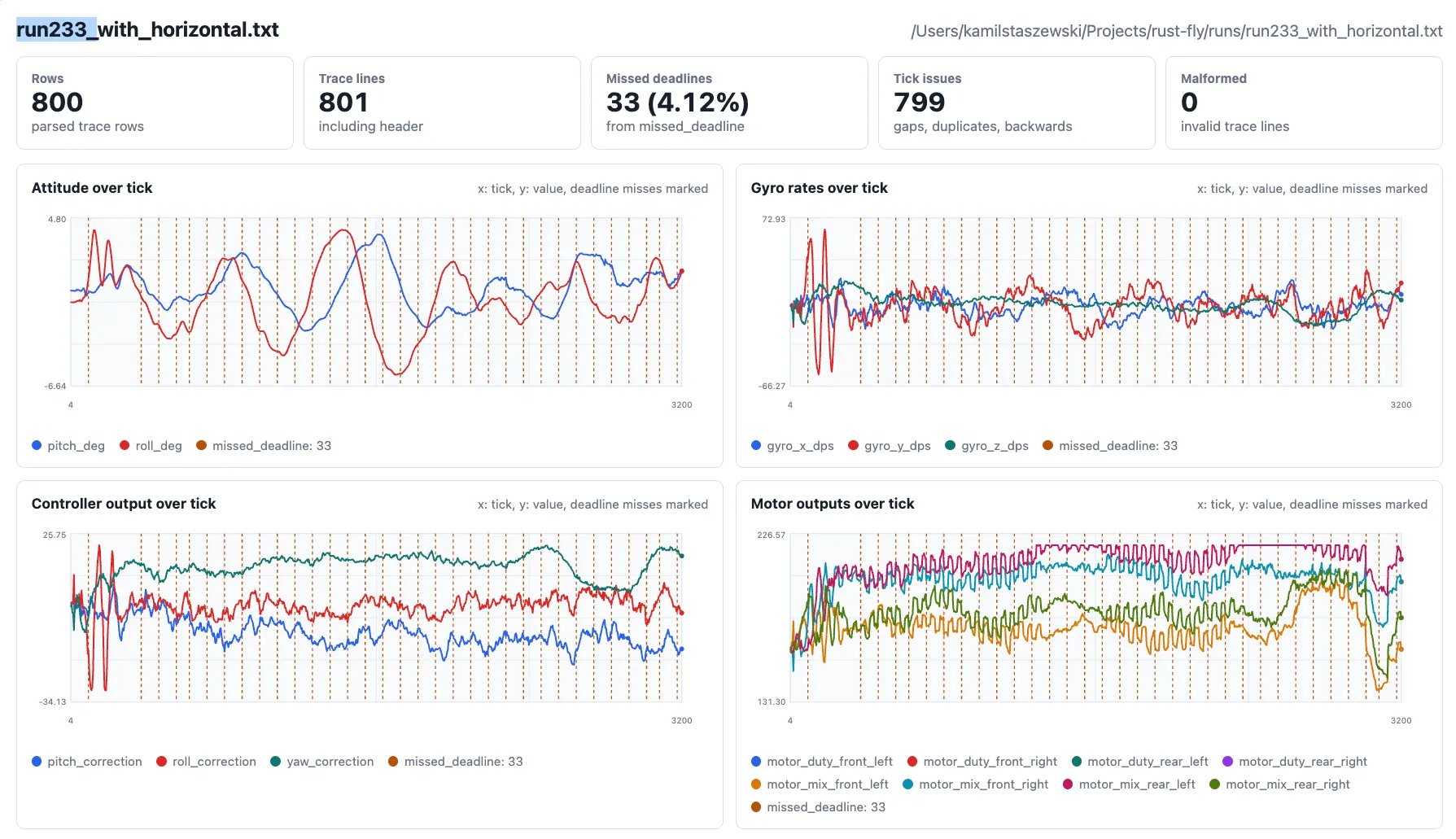
Thanks to these two, I actually could interpret each failure. I could try to tweak params across the runs instead of guessing. I started asking a more specific questions like:
- Was the height or velocity estimate wrong?
- Did the controller request the wrong correction?
- Did mixing or runtime authorization change the final duties?
Example from one of the runs. When altitude oscillated, the trace showed whether the drone was reacting to incorrect height measurements or whether the velocity controller was requesting corrections too aggressively.
Trade-offs
Of course, there were trade-offs. Separation introduced more code - structs, explicit inputs and outputs, validation, and necessary wiring. It made some tasks tedious. Changes to one contract required updates across several modules and tests. There is also a runtime cost. Estimation, validation, tracing, and safety checks all consume CPU time and memory on a small ESP32-S3. The active path therefore had to remain bounded and allocation-free, while expensive trace formatting and flash writes happened outside the control loop.
Project got me into thinking about safety of the program. Not only in the case of small hobby drone, but overall - how they do it in jets or critical infrastructure. This way I got to know a JPL’s Power of 10 and JSF Air Vehicle C++ standard. It got especially intensified in the last few days, with recent video of Tiger Beetle where Gerald Holzman talked about rules for safety critical coding. Worth mentioning that I first heard about it in LaurieWired’s “Why Fighter Jets Ban 90% of C++ Features”
The benefit was that state ownership and failure behaviour became visible. Estimators could be tested without hardware, controllers without motors, and the mixer without sensors. Traces could show where a decision changed instead of presenting only raw measurements and final PWM duties. This architecture is not universal or formally certified. It was designed around StampFly’s sensors through trial and error; actuator limits, timing, and the conditions in which I tested it. The separation makes assumptions easier to inspect, but it does not automatically make those assumptions correct.
Lessons learned
I started this project expecting the main challenge to be implementing control equations in Rust. I was also afraid that my rust skills are too basic for this kind of a project. At first, it was indeed moving slowly, feeling a little uneasy that I might not make it. I was wrong I made it and I learned a lot.
I understood that the final system is a progression from uncertainty to authority. Sensors provide incomplete evidence. Estimators form a belief about motion. Controllers request change. Policies and the mixer translate that request into something physically achievable.